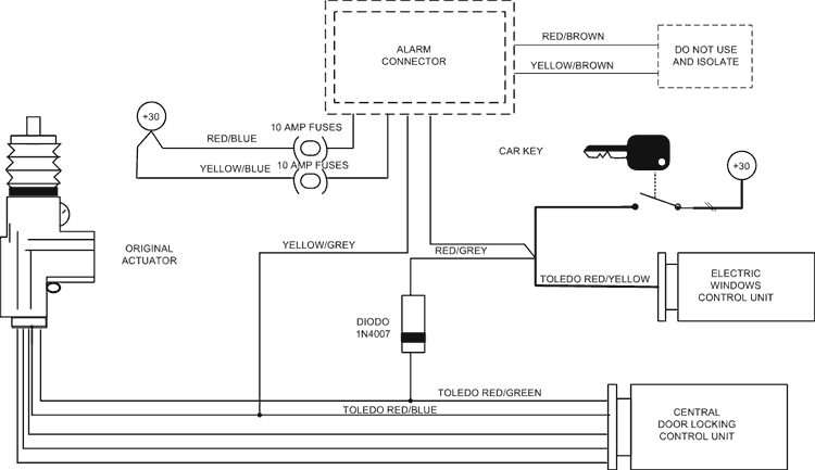

For BMW vehicles with automatic closure of windows and sunroof operating in the door’s lock. To obtain the same facility fit one diode only. Other modules are not necessary.

FOR VEHICLES EQUIPPED WITH CENTRAL DOOR LOCKING BY AN INTERNAL SWITCH THAT SUPPLIES THE NEGATIVE. (Chrysler).

For vehicles equipped with a positive command actuator in the driver’s door (Renault.ect.).

For vehicles with negative command actuator in the driver’s door (Fiat. ect.).

For vehicles without actuator in the driver’s door (Peugeot, Volvo, ect.).

For vehicles without CENTRAL DOOR LOCKING (i.e. Mercedes, ect.)
.
For vehicles equipped with a dip switch in the driver’s door only (i.e. Saab etc.).

For Jaguar, Opel Calibra, Omega, Vectra and Audi A4 equipped with automatic closure of windows and roof in one of the front doors. Fit one diode only, other modules are not necessary.

For Volkswagen Golf series 3 with automatic closure of windows and roof in one of the front doors. Cut the GREEN wire at the compressor. Other modules are not necessary.


Remove any items that may create a false alarm through movement inside the vehicle (i.e. furry dice). Close the doors and leave just enough room through one window to introduce an arm. Introduce you arm through the gap and move it around. The dashboard mounted LED will illuminate as the sensors detect movement. If you turn the adjuster screw clockwise, the sensitivity decreases if you turn the screw anticlockwise. Beware that it is possible to increase sensitivity to a point at which it will become too sensitive and may cause false alarms. To check that it is not over sensitive, thump the front and rear windows with your hand (care should be taken no damage the window!). This thumping should not illuminate the LED. After setting up the sensors, press one of the handset buttons or turn the ignition ON. This isolates the test condition.
NOTE: If the TEST condition is required again, disarm the alarm, disconnect the negative terminal of the vehicle battery for about 10 seconds and then reconnect the battery terminal.
The impulse generated by opening the boot, the bonnet or the door is detected by the alarm and causes it to sound.
If you disconnect the power supply wires (when the alarm is armed) the siren will sound.
The siren is equipped with nickel-cadmium batteries that slowly lose their charge. The siren will recharge within 12 hours after vehicle battery connection.
The alarm system is supplied with two dual-channel transmitters equipped with an extremely secure rolling code which changes at every press of the command buttons. The transmitters supplied are pre-coded. For additional transmitters: ensure that the alarm is disarmed, turn the ignition key to ON and move dip switch No.2 to the "ON" position. Press the ARM/DISARM button of the new transmitter until the check led switches off. If you are self-coding to replace a lost transmitter, repeat the self-coding process on all remaining transmitters a total eight times to remove the code of the old transmitter. Move dip switch No.2 to the "OFF" position and turn OFF the ignition key/ To check the self-coding, arm and disarm the system.
N.B. If you release the ARM/DISARM button of the transmitter before the check LED switches off, the transmitter won' t be coded.
| Input voltage: | 12 VDC +/- 4 VDC. |
| Current draw: | check led < 2 mA. |
| Current draw: | armed alarm < 17 mA. |
| Current draw: | disarmed alarm < 5 mA |
| Sound cycles: | 3 of 29" for each sensor. |
| Working temperature: | from -40 to +85 C |
| Engine immobilizations relay contact capacity: | 10 Amp - 15 VDC |
| Visual signaling relay contact capacity: | 10 Amp - 15 VDC |
| Central door locking relay contact capacity: | 10 Amp - 15 VDC |
| Arming delay: | 60" for doors, ultrasonic and additional sensors. 5" for ignition switched live, boot and/or bonnet. |
| Sound power: | in conformity with the 70/388 EEC directive. |